I recently purchased a Tuya-based RGB ceiling light on Amazon (https://amzn.eu/d/80xtOv5) that can be controlled through the Tuya / Smart Life mobile application. Initially, my plan was to keep the original Tuya firmware and integrate the lamp locally into Home Assistant using LocalTuya, in order to control the light without relying on the Tuya cloud. However, as I discovered along the way, the Tuya firmware can be replaced with ESPHome.
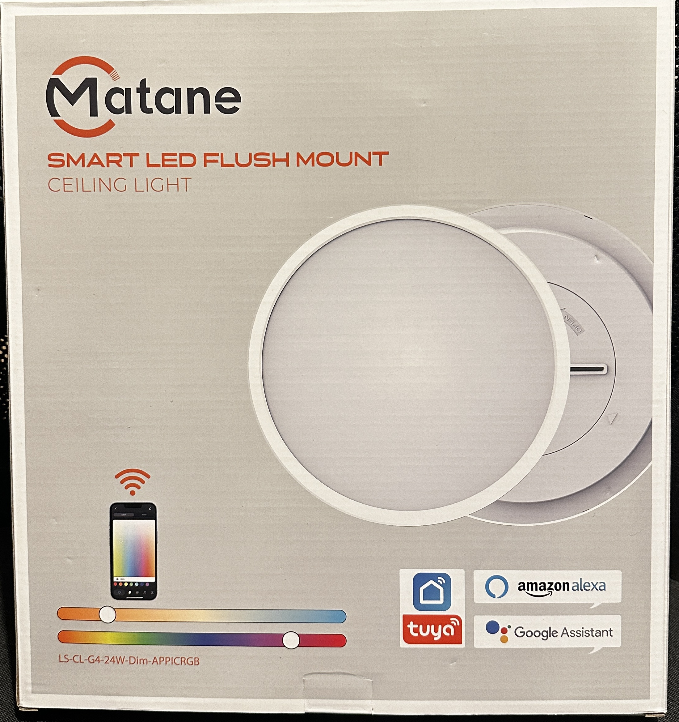
But let’s start from the beginning. The ceiling light is sold under the model number LS-CL-G4-24W-Dim-APPICRGB by the brand Matane and is manufactured by the company Shenzen Longtime Metals Co., Ltd.. The packaging prominently shows color bars indicating RGB color control as well as warm and cold white lighting. As expected, the box also displays the usual logos of a product that is part of the Tuya ecosystem.
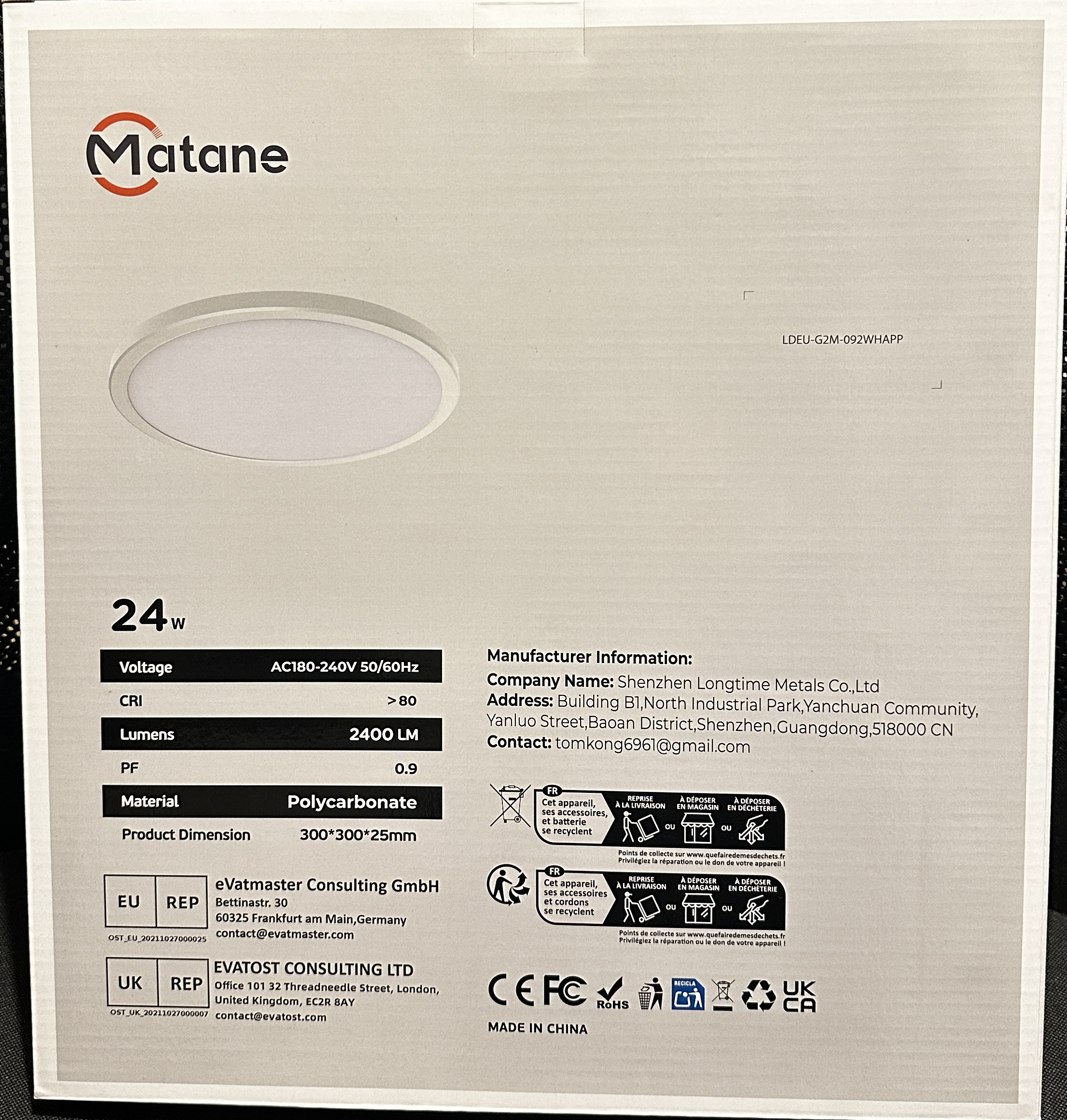
According to the specifications in the user manual, the lamp is rated at 24 W for the main white light and an additional 8 W for RGB lighting, with a total luminous flux of 2400 lumens. The supported color temperature range is listed as 3000 K to 6500 K.

Analyzing the Hardware
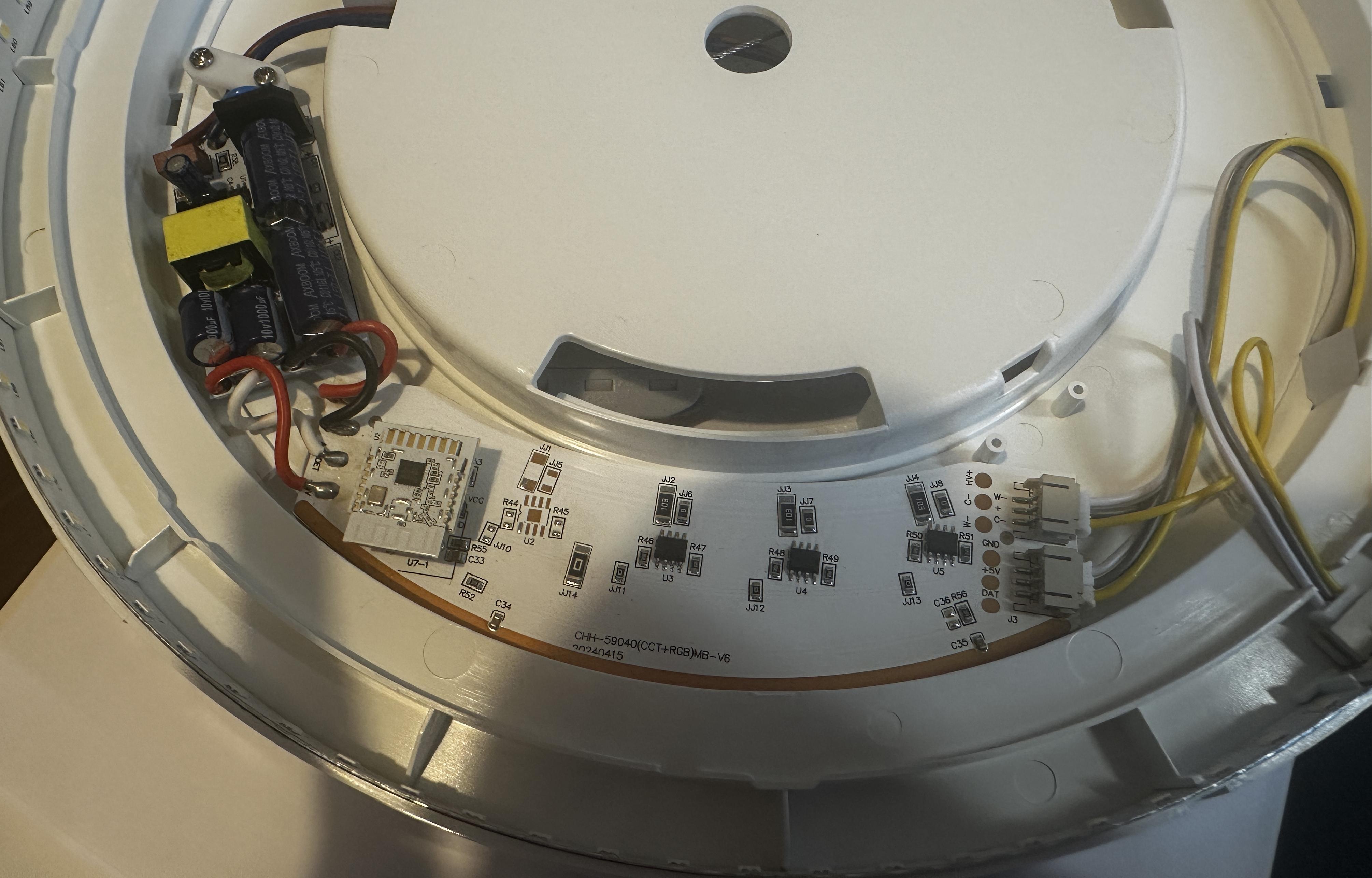
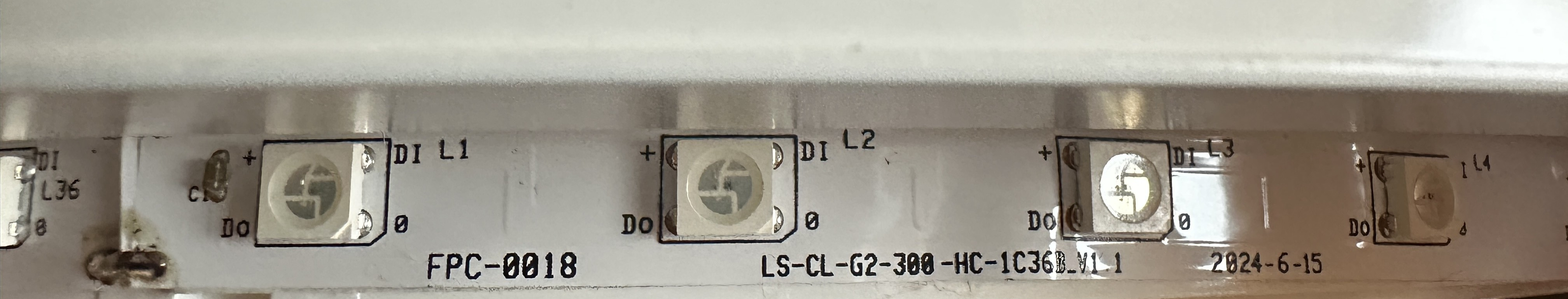
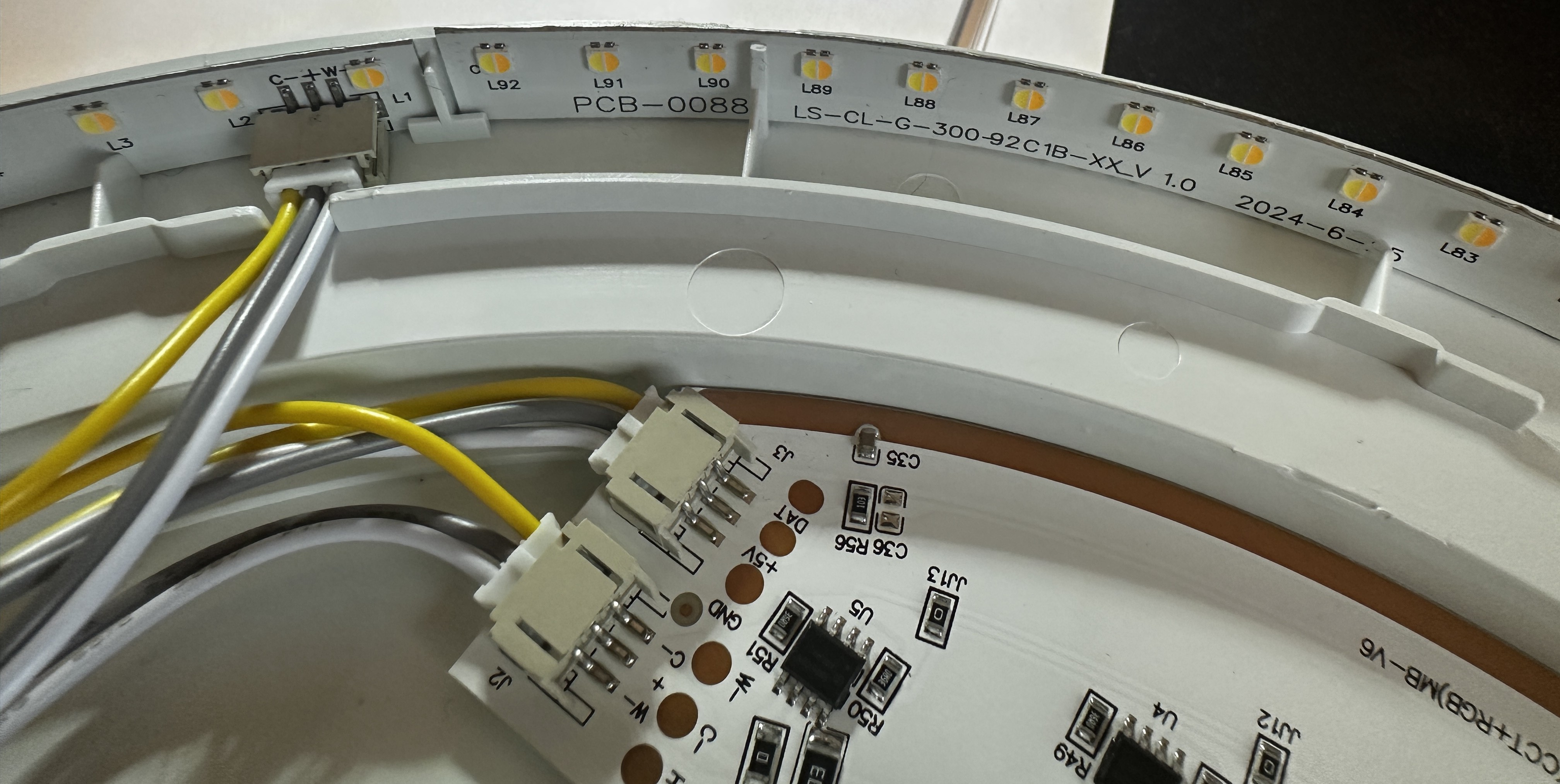
With that in mind, the next step was to open the lamp and take a closer look at the internal hardware. After removing the housing using plastic pry tools and taking out the diffuser, the internal components of the lamp became accessible. The main PCB is connected to the power supply on one side and to two distinct LED strips on the other: one strip consisting of 92 white LEDs, and a second strip containing 36 RGB LEDs. In addition, a Tuya CBU module is mounted on a pin header and serves as the central controller for the entire device. Some research revealed that the CBU module is supported by LibreTiny, which in turn makes it compatible with ESPHome. We will flash ESPHome a little later; first, we will take a closer look at the circuitry.
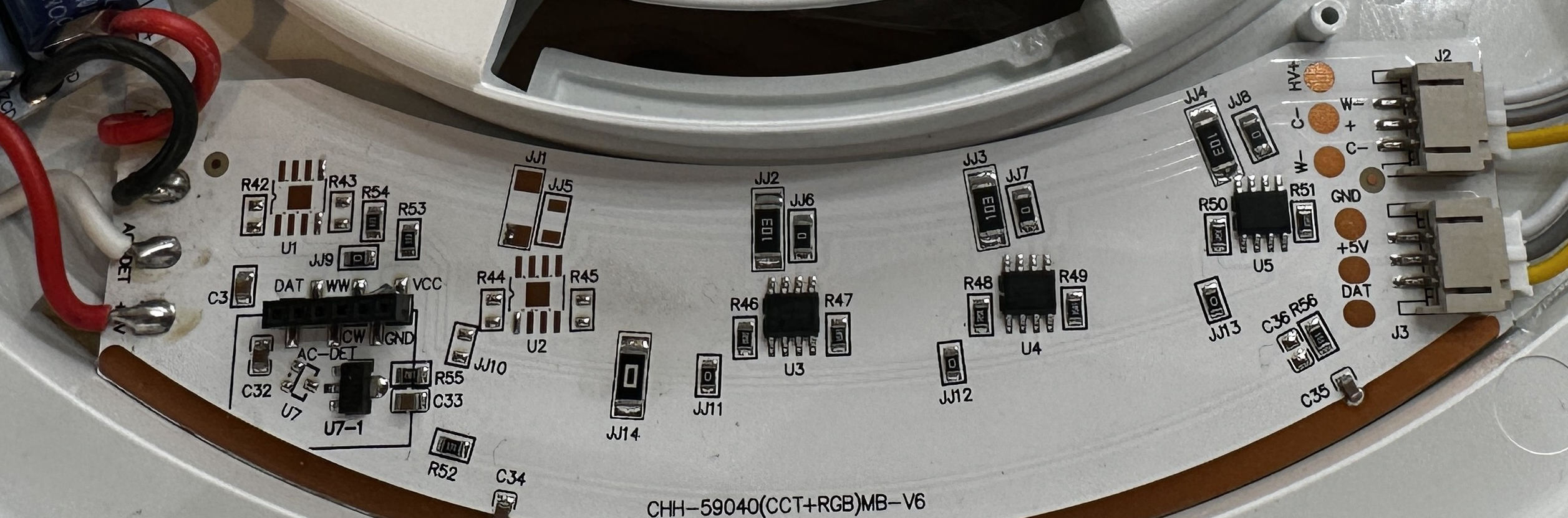
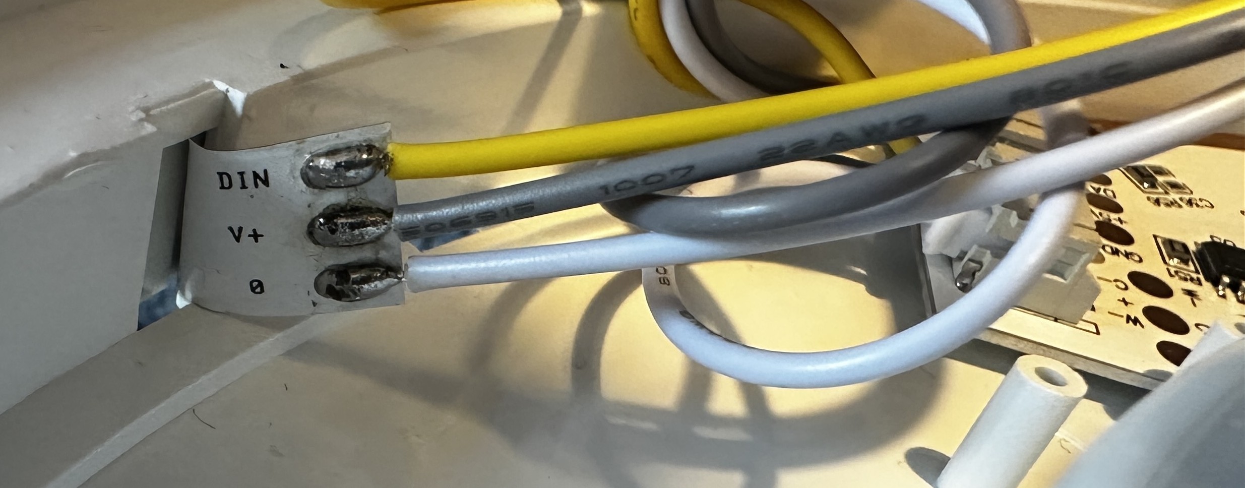
After removing the CBU module from the pin header, the silkscreen labels next to the connector become visible. Both the pin header and the corresponding connector on the PCB are labeled with Z, DAT, WW, CW, GND, and VCC. Using continuity tests, these signals can be traced across the PCB. The Z pin does not appear to be connected anywhere. The DAT pin is directly connected to the DIN input of the RGB LED strip, specifically to the first RGB LED in the chain (L36). The RGB strip is daisy-chained (DIN → DOUT → DIN …), which strongly indicates a WS2812-style single-wire protocol.
The WW and CW pins are routed to the DIM1 and DIM2 PWM inputs of three identical SM2612EN LED controller chips (datasheet available here). These chips act as low-side constant-current drivers for the white LED strip. Their outputs, OUT1 and OUT2, are connected to the warm-white and cold-white LED channels respectively, allowing the color temperature of the white light to be adjusted by independently controlling the current through each channel (Correlated Color Temperature, CCT).
At this point, it was clear that the lamp uses a typical RGB+CCT design, with separate LED subsystems for color lighting and white illumination. To finalize the tracing of the connections, we need to map the pins of the CBU resp. it’s SoC - the Beken BK7231N - to the LED signals. The datasheet of the CBU module gives us the relevant pin numbers, which we’ll need for the ESPHome configuration later.
| CBU Pin | BK7231N Pin | Function |
|---|---|---|
| Pin 2 | P16 | DAT (RGB Data) |
| Pin 9 | P6 | WW (Warm White) |
| Pin 10 | P7 | CW (Cold White) |
Flashing ESPHome
According to the flashing guide, the BK7231N is flashed via the serial UART1 connection. For that, we solder to the pins 15 (TX1) and 16 (RX1) of the CBU module as well as to the pins 13 for GND and 14 for 3V3. Optionally wiring to UART2 (pins 6 and 7) can be used to get the log output, just to see what’s going on.
Please note: Do not power the device from mains while flashing. The lamp must be completely disconnected from AC power during UART flashing.

A USB-to-UART adapter operating at 3.3 V logic levels is required. The flashing guide also recommends to use a separate power supply. The connections are as follows:
| CBU Pad | USB-UART Adapter | Power Supply |
|---|---|---|
| UART_TX1 | RX | - |
| UART_RX1 | TX | - |
| GND | GND | GND |
| 3.3 V | - | 3.3V |
With the serial connection in place, the next step is to verify communication with the chip using ltchiptool. I am using ltchiptool via uv, but the commands work the same in other setups. First, let’s verify that the BK7231N is detected correctly:
$ uv run ltchiptool flash info beken-7231n --device /dev/ttyUSB0
I: Connecting to 'Beken 7231N' on /dev/ttyUSB0 @ 115200
I: |-- Success! Chip info: BK7231N
I: Reading chip info...
I: Chip: BK7231N
I: +-----------------------+-------------------------------------+
I: | Name                  | Value                               |
I: +-----------------------+-------------------------------------+
I: | Protocol Type         | FULL                                |
I: | Chip Type             | BK7231N                             |
I: | Bootloader Type       | BK7231N 1.0.1                       |
I: | Chip ID               | 0x7231c                             |
I: | Boot Version String   | N/A                                 |
I: |                       |                                     |
I: | MAC Address           | [...]                               |
I: |                       |                                     |
I: | Flash ID              | EB 60 15                            |
I: | Flash Size (by ID)    | 2 MiB                               |
I: | Flash Size (detected) | 2 MiB                               |
I: |                       |                                     |
I: | Encryption Key        | [...]                               |
I: +-----------------------+-------------------------------------+
I: |-- Finished in 2.046 s
This confirms that interaction with the chip over UART works as expected. Before flashing ESPHome, it is recommended to create a full backup of the original Tuya firmware. This allows restoring the device, if anything goes wrong.
$ uv run ltchiptool flash read --device /dev/ttyUSB0 beken-7231n ltchiptool_flash-dump.bin
Now we need to create the ESPHome firmware. For that, I use my docker-based ESPHome Device Builder with the following configuration. The resulting firmware file deckenlampe.uf2 can be downloaded.
esphome:
  name: deckenlampe

bk72xx:
  board: cbu

wifi:
  ssid: !secret wifi_ssid
  password: !secret wifi_password

  # Fallback AP
  ap:
    ssid: "Beken_Ceiling_Light"
    password: !secret ap_password

logger:

api:
  encryption:
    key: !secret encryption_key

ota:
  - platform: esphome
    password: !secret ota_password

# PWM outputs for the CCT white channels
output:
  - platform: libretiny_pwm
    id: pwm_cw
    pin: P7   # CBU Pin 10 -> CW (Cold White)

  - platform: libretiny_pwm
    id: pwm_ww
    pin: P6   # CBU Pin 9 -> WW (Warm White)

light:
  # RGB LED strip (WS2812-style)
  - platform: beken_spi_led_strip
    name: "Deckenlampe RGB"
    pin: P16        # CBU Pin 2 -> DAT
    num_leds: 36
    chipset: ws2812
    rgb_order: GRB
    restore_mode: RESTORE_DEFAULT_ON

  # White LEDs (CCT)
  - platform: cwww
    name: "Deckenlampe Weiß"
    cold_white: pwm_cw
    warm_white: pwm_ww
    cold_white_color_temperature: 6500 K
    warm_white_color_temperature: 2700 K
    restore_mode: RESTORE_DEFAULT_ON
Flashing the downloaded firmware is done as follows:
$ uv run ltchiptool flash write --device /dev/ttyUSB0 deckenlampe.uf2
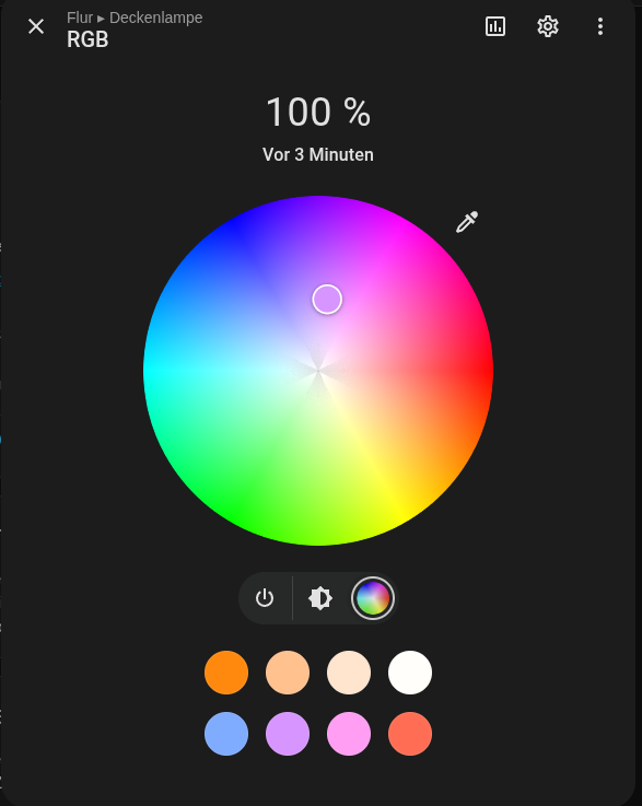
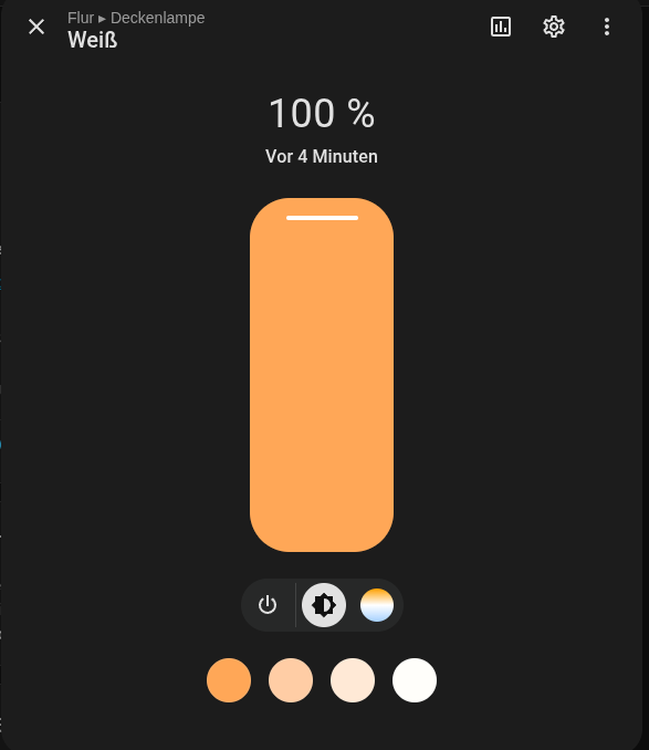
After flashing completes successfully, the lamp reboots and connects to the Wi-Fi. At this point, it becomes available in Home Assistant via the ESPHome integration. Both LED strips of the light can be controlled separately.
Finally, once reassembled and mounted, the ceiling light looks as shown below. Both LED strips are visible: the upper RGB strip and the lower white (CCT) strip.
